Electric circuit

An electric circuit is a connection of components that can conduct electric current. Simple electrical circuits have conductors (usually wires), a component that supplies power (like a battery or wall plug) and a component that absorbs power called the load. A light bulb would be an example of a load and there must always be a return path so the electrons have a way to come back to the power source from the load. Every circuit is designed to deliver power to one or more loads. For example, in a boombox the power goes to the speakers. Similarly, the power in a lamp goes to the light bulb. The circuit allows the charge to leave from one side of the power supply and come back on the other side of the power supply.
Circuits can be in series, parallel or a combination of the two referred to as a series-parallel circuit.[2] To read more on these differing circuit layouts, visit: series circuit and parallel circuit.
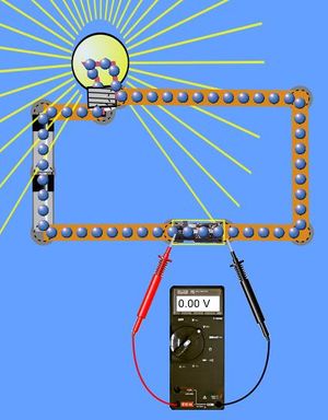
In Figure 1, the circuit is closed (the charge can leave from the supply, go through the light bulb and come back to the supply) and the light bulb acts as the load. Notice that the voltmeter reading displays 0 V because there is 0 voltage drop across the electric switch.[1]
Open circuit

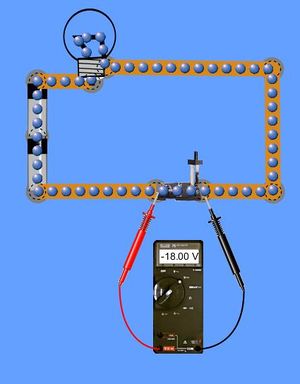
An open circuit (like the one in Figure 2) has a physical break in the conduction path where current drops to 0 and resistance becomes infinite (far too high for an ohmmeter to measure). Voltage however can be measured because the voltmeter connects across the open terminal.[3] Note the open circuit is not a true circuit because the charge from one side of the power supply can't leave and come back to the other side of the power supply.
In Figure 2, the switch is lifted therefore opening the circuit meaning the current does not have a complete path and the light bulb does not function. The voltmeter can still be connected and displays a reading of 18 volts due to the presence of the two 9 V batteries in series.[1]
It doesn't matter where the break in the electric circuit is, any interruption of the path will stop the electric current from moving around in its path. This is the basis of an electric switch discussed above.
Short circuit

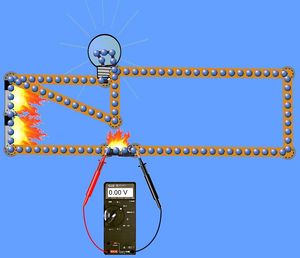
A short circuit (shown in Figure 3) is an unintentional low resistance connection between two or more points in a circuit. Since current increases as the resistance drops (given by Ohm's law), this will result in a large amount of current flowing through the "short." This higher current, if it is greater than the wire gauge can safely handle, has the potential to burn the current path due to high temperatures, and could cause a fire. This results in shorting the circuit.[3] Safety devices such as fuses and circuit breakers are used in the case of a short circuit to prevent the shock hazards and damage associated with it.
In Figure 3, a short circuit is present. Although some of the current still goes through the light bulb, the path bypassing the light bulb offers the lowest resistance for the circuit. This lower resistance equates to a significantly larger current. This high amount of current surpasses the current rating of the wire thereby destroying the switch and burning part of the current path.[1]
Phet Simulation
The University of Colorado has graciously allowed us to use the following Phet simulation. This simulation explores how batteries work in an electric circuit:
For Further Reading
For further information please see the related pages below:
- Direct current
- Energy for electricity by country
- Electrical grid
- Electric generator
- Or explore a random page!
References
- ↑ 1.0 1.1 1.2 1.3 1.4 1.5 University of Colorado (2011). Circuit Construction Kit (DC Only), Virtual Lab [Online]. Available http://phet.colorado.edu/en/simulation/circuit-construction-kit-dc-virtual-lab
- ↑ R.T. Paynter, “Basic Electric Components and Meters,” in Introduction to Electricity, 1rst ed. NJ: Prentice-Hall, 2011, ch. 4, sec. 4.3, pp. 155-160.
- ↑ 3.0 3.1 R.T. Paynter, “Basic Electric Components and Meters,” in Introduction to Electricity, 1rst ed. NJ: Prentice-Hall, 2011, ch. 4, sec. 4.4, pp. 160-162.

