Grounding

Electrical grounding, otherwise known as earthing, primarily provides a measure of safety against electric shocks by acting as a safety line to redirect electric current in the event of short circuits. For household appliances, this is accomplished by a three-pronged electrical outlet with a dedicated grounding prong.[2]
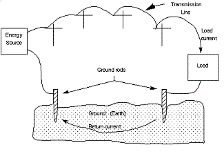
Grounding is also a way of providing a current return path in some electrical transmission systems. Since the earth is an electrically neutral body, it is said that the ground, or earth, is at zero electric potential, and all other voltages are determined relative to this ground potential. This allows the ground to function as an extended neutral line in that it completes the transmission electric circuit by acting as a source of electrons for the electric generator and as an endpoint for electrons after the electrical load. This means that instead of a wire that provides a current return path from the load back to the voltage source as seen in most simple circuits, the ground acts as that return path.[3]
However, this use of grounding is only employed in a Single Wire Earth Return transmission system, which is mainly used in some rural areas in countries like Canada and Australia.[4] Most modern transmission systems use three-phase electric power, which does not use grounding as a return path.
A major issue with using the ground as an electrical conductor is that it has a high electrical resistance, making it very inefficient as a means of transmitting power. However, this issue is partially addressed by inserting the ground rods (located at the generator and after the load) fairly deep into the ground. Since the resistance of a conductor is inversely proportional to its cross-sectional area, making the rods deeper reduces the total resistance by increasing the area through which the current travels between the rods. For more information about the factors that determine resistance, see resistance.
In Residential Systems
A continuous low resistance grounding path in residential electrical systems ensures that voltage levels in the wiring are stable and makes overload protection devices (circuit breakers, fuses) as effective as possible. In a typical grounding circuit the neutral line connects to a neutral bar (in the service panel) which connects to a ground clamp on the water or gas pipes. These pipes go underground and establish a direct ground connection. Alternatively, the neutral bar can connect to an underground grounding rod located outside of the residence to establish a direct ground connection. There must be no breaks in the ground line, so parallel connections must be made with anything that can break the ground path, such as a water meter.[5]
In the presence of water, an electrical outlet can be dangerous as the water often provides a direct ground connection for the current passing through the outlet, posing a serious shock hazard. Ground fault circuit interrupters are used as a safety measure to protect against this possibility.
References
- ↑ EECS, UC Berkeley. (July 30, 2015). Lab Logistics [Online], Available: http://www-inst.eecs.berkeley.edu/~ee100/su04/lab/lab1/new_intro_lab_guide_report.pdf
- ↑ Hyperphysics. (July 30, 2015). Breakers and Ground Wires [Online]. Available: http://hyperphysics.phy-astr.gsu.edu/hbase/electric/bregnd.html
- ↑ G. Hunka. (July 30, 2015). Circuit Grounds and Grounding Practices [Online]. Available: http://www.ese.upenn.edu/detkin/instruments/misctutorials/Ground/grd.html
- ↑ P. Armstrong. (July 30, 2015). Single Wire Earth Return (SWER) [Online]. Available: http://www.stonepower.se/Images/SWER.pdf
- ↑ R.T. Paynter, “Basic Electric Components and Meters,” in Introduction to Electricity, 1rst ed. NJ: Prentice-Hall, 2011, ch. 8, sec. 8.1, pp. 331-340.

