DC generation

Direct current generation can be quite similar to AC generation, in that the electromagnetic generation of energy still requires all the same essential components. However, direct current is generated by photovoltaic cells and batteries. Direct current generators are rare in major power plants due to the prevalent use of alternating current over direct current in transmission lines. Direct current generation is therefore limited mainly to small-scale generators.
Theory
Faraday's Law states that a changing magnetic flux on a looped conductor will produce a magnetic force that causes the electrons in the conductor to move, creating an electric current. This is known as electromagnetic induction, and it is the fundamental principle underlying electrical generators. The magnetic force applied to the electrons creates what is known as an electromotive force, and that is what drives the electrons in the electric circuit. The strength and direction of the electromotive force is determined by the strength and direction of the magnetic field and the velocity of the moving part of the generator, which could be either the conductor or the magnet.[2]
For an animation that shows this theory in practice, visit AC generation. Remember, DC and AC will have the same essential components. The ability for the DC current to not have an alternating current is explained in the next section.
Generator

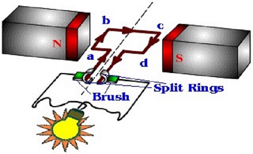
Electrical current is generated when a rotating loop of wire, known as an armature, is placed in a uniform magnetic field, or when a stationary armature is placed in a rotating magnetic field. In the first case, as the armature rotates, one half of the loop will always be moving in the opposite direction of the other half of the loop. This causes an electromotive force in opposite directions for both halves of the armature, which add together to allow a current to flow through the loop (see Figure 2).[4] The same result can be achieved with a rotating magnet around a stationary armature.
The basic layout of a traditional direct current generator is quite similar to that of an alternating current generator, except for the addition of a split-ring commutator (See Figure 1). Each arm of the armature is connected to a half of the split-ring, and this ring rotates with the armature. As the ring rotates, it slips against metal brushes (See Figure 2). This combination of a split-ring and slipping metal brushes compose the split-ring commutator. As seen in Figure 2, the split-ring ensures that the brush that an arm of the armature connects to changes once every full revolution. This fundamental fact is key to generating direct current.
Say the armature in Figure 2 is rotating clockwise. Initially, the magnetic field is oriented such that the generated current flows counter-clockwise and comes out of the left arm of the armature, into the circuit, and back through the right arm of the armature. Say the arm of the armature on the left side is arm A and the arm on the right is arm D, just as it is labelled in the diagram. Once more than a quarter of a revolution has passed, arm A will have switched direction and the segment of its velocity that is perpendicular to the magnetic field is now directed downwards, whereas it was directed upwards until this point. In an AC generator, the current would change direction at this point. As the electromotive force in the armature reverses, so does the current flow, as it then begins to flow clockwise. The current will then be coming out of arm D. However, due to the split-ring commutator, arm D is now connected to the brush on the left side, so the current continues to flow through the circuit from the brush on the left to the one on the right, exactly as it was previously. Therefore, the split-ring commutator essentially serves to counteract the reversal of current that occurs in AC generators.
For Further Reading
For further information please see the related pages below:
- Direct current
- Electric current
- Electrical generation
- Or explore a random page!
References
- ↑ R. Fitzpatrick. (2007, July 14). The Direct Current Generator [Online]. Available: http://farside.ph.utexas.edu/teaching/302l/lectures/node91.html
- ↑ Faraday's Law [Online]. Available: http://hyperphysics.phy-astr.gsu.edu/hbase/electric/farlaw.html#c1
- ↑ DC Generator [Online]. Available: http://www.ncert.nic.in/html/learning_basket/electricity/electricity/machine/dc_generator.htm
- ↑ AC Generator [Online]. Available: http://hyperphysics.phy-astr.gsu.edu/hbase/magnetic/motorac.html#c2

