Otto cycle
The Otto Cycle, describes how heat engines turn gasoline into motion. Like other thermodynamic cycles, this cycle turns chemical energy into thermal energy and then into motion. The Otto cycle describes how internal combustion engines (that use gasoline) work, like automobiles and lawn mowers.
Application
The Otto Cycle provides the energy for most transportation and was essential for the modern world. Specifically, the vast majority of automobiles seen on the road today use the Otto Cycle to convert gasoline into motion. Any machine (the list[1] would go on and on) that uses gasoline will be divided into two categories of engines as seen below.
- Types of engines that use the Otto Cycle
- Figure 1. A two stroke engine[2]
- Figure 2. A four stroke engine[3]
The engines' pages will provide details on their unique mechanisms, and an explanation on how they use the Otto Cycle, which is slightly modified.
The Ideal Otto Cycle
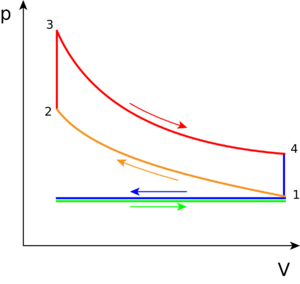
The PV diagram (pressure-volume diagram) of the ideal Otto cycle is shown in Figure 3. This diagram models how the changes in pressure and volume of the working fluid (gasoline and air fuel) change due to the combustion of hydrocarbons which powers the movements of a piston, creating heat, to provide motion for a vehicle. There are expansion (increased volume chamber) piston motions—caused when the thermal energy is released from combustion—inducing work being done by the gas and on the piston. In contrast, when the piston does work on the gas, the engine chamber is being compressed (decreasing in volume).[5]
It is important to note that Figure 3 depicts an ideal process for any engine using the Otto cycle. It describes the basic working steps in a gasoline engine. The slight modification which depicts a more realistic situation of the Otto Cycle's PV diagram for a two stroke and four stroke engine is explained on their respective pages. The work done by the engine can be calculated by solving the area of the closed cycle.
The following describes what occurs during each step on the PV diagram, in which the combustion of the working fluid—gasoline and air (oxygen), changes the motion in the piston:
Green line: Referred to as the intake phase, the piston is drawn down to the bottom to allow the volume in the chamber to increase so it can "intake" a fuel-air mixture. In terms of thermodynamics, this is referred to as an isobaric process.
Process 1 to 2: During this phase the piston will be drawn up, so it can compress the fuel-air mixture that entered the chamber. The compression causes the mixture to increase slightly in pressure and temperature—however, no heat is exchanged. In terms of thermodynamics, this is referred to as an adiabatic process. When the cycle reaches point 2, that is when the fuel is met by the spark plug to be ignited.
Process 2 to 3: This is where combustion occurs due to the ignition of fuel by the spark plug. The combustion of the gas is complete at point 3, which results in a highly pressurized chamber that has a lot of heat (thermal energy). In terms of thermodynamics, this is referred to as an isochoric process.
Process 3 to 4: The thermal energy in the chamber as a result of combustion is used to do work on the piston—which pushes the piston down—increasing the volume of the chamber. This is also known as the power stoke because it is when the thermal energy is turned into motion to power the machine or vehicle.
Purple line (Process 4 to 1 and exhaust phase): From process 4 to 1, all waste heat is expelled from the engine chamber. As the heat leaves the gas, the molecules lose kinetic energy causing the decrease in pressure.[6] Then the exhaust phase occurs when the remaining mixture in the chamber is compressed by the piston to be "exhausted" out, without changing the pressure.
For Further Reading
- Two stroke engine and Four stroke engine
- Heat engine
- PV diagram
- Combustion
- Gasoline
- Diesel vs gasoline engine
- Or explore a random page!
References
- ↑ A partial list would include motorcycles, pick-up trucks, vans, SUVs, lawn mowers, cars, many boats and even some portable generators.
- ↑ Wikimedia Commons [Online], Available:https://commons.wikimedia.org/wiki/File:Two-Stroke_Engine.gif
- ↑ "File:4StrokeEngine Ortho 3D Small.gif - Wikimedia Commons", Commons.wikimedia.org, 2018. [Online]. Available: https://commons.wikimedia.org/wiki/File%3A4StrokeEngine_Ortho_3D_Small.gif. [Accessed: 17- May- 2018]
- ↑ Wikimedia Commons [Online], Available: https://en.wikipedia.org/wiki/Otto_cycle#/media/File:P-V_Otto_cycle.svg
- ↑ Internal Combustion Engine Basics", Energy.gov, 2018. [Online]. Available: https://www.energy.gov/eere/vehicles/articles/internal-combustion-engine-basics. [Accessed: 28- May- 2018].
- ↑ I. Dinçer and C. Zamfirescu, Advanced power generation systems. London, UK: Academic Press is an imprint of Elsevier, 2014, p. 266.


![Figure 1. A two stroke engine[2]](/wiki/images/f/ff/Two-Stroke-Engine.gif)
![Figure 2. A four stroke engine[3]](/wiki/images/4/47/4StrokeEngine.gif)
