Transformer

A transformer is an electrical device that uses electromagnetic induction to pass an alternating current (AC) signal from one electric circuit to another, often changing (or "transforming") the voltage and electric current. Transformers do not pass direct current (DC), and can be used to take the DC voltage (the constant voltage) out of a signal while keeping the part that changes (the AC voltage). In the electrical grid transformers are key to changing the voltages to reduce how much energy is lost in electrical transmission.
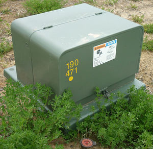
Transformers change the voltage of the electrical signal coming out of the power plant, usually increasing (also known as "stepping up") the voltage. Transformers also reduce ("step down") the voltage in substations, and as distribution transformers.[2] Transformers are also used as a part of devices, like current transformers.
How transformers work
It often seems surprising that a transformer keeps the total power the same when voltage goes up or down. One must keep in mind that when the voltage goes up, the current goes down:
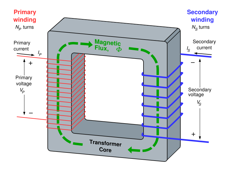
Transformers use electromagnetic induction to change the voltage and current. This change is called transformer action, and describes how the transformer changes an AC signal from its primary to its secondary component (like in the equation above). When an AC signal is applied to the primary coil, the changing current causes a magnetic field to change (get bigger or smaller). This changing magnetic field (and associated magnetic flux) will pass through to the secondary coil inducing a voltage across the secondary coil, thereby effectively coupling the AC input from the primary to secondary component of the transformer. The voltage applied to the primary component will also be present in the secondary component.
As mentioned before, transformers do not allow DC input to flow through. This is known as DC isolation.[2] This is because a change in current cannot be generated by DC; meaning that there is no changing magnetic field to induce a voltage across the secondary component.

The fundamental principle that allows transformers to change the voltage of alternating current is the direct relationship between the ratio of loops of wire in the primary winding to the secondary winding and the ratio of the primary voltage to the output voltage. The ratio between the number of turns (or loops) in the primary coil to the number of turns in the secondary coil is known as the turns ratio. The turns ratio establishes the following relationship with voltage:
- = Number of turns in the primary coil
- = Number of turns in the secondary coil
- = Voltage across the primary
- = Voltage across the secondary
- = Current through the primary
- = Current through the secondary
From this equation, if the number of turns in the primary coil is greater than the number of turns in the secondary coil (), then the voltage across the secondary coil will be less than in the primary coil. This is known as a "step-down" transformer, because it lowers, or steps down, the voltage. The table below shows common types of transformers used on the electrical grid.
| Transformer Type | Voltage | Turns ratio | Current | Power |
| Step down | input (primary) voltage > output (secondary) voltage | p>s | p<s | p=s |
| Step up | input (primary) voltage < output (secondary) voltage | p<s | p>s | p=s |
| One-to-one | input (primary) voltage = output (secondary) voltage | p=s | p=s | p=s |
The one to one transformer will have equal values for everything and is used mainly for the purpose of providing DC isolation.
A step down transformer will have a higher primary voltage than secondary voltage, but a lower primary current value than its secondary component.
In the case of the step up transformer, the primary voltage will be lower than the secondary voltage, meaning a greater primary current than the secondary component.
Efficiency
Under ideal conditions the voltage and current change by the same factor for any transformer, which explains why the primary power value is equal to the secondary power value for each case in the above table. As one value decreases the other increases to keep at a constant equilibrium power level.[2]
Transformers can be extremely efficient. High-power transformers can reach the 99% mark of efficiency, as a result of successes in minimizing transformer losses. However, a transformer will always output a slightly lower power than its input, as losses cannot be eliminated completely. There is some transformer impedance.
To learn more about transformers please see hyperphysics.
For Further Reading
For further information please see the related pages below:
- Electrical transmission
- Electrical grid
- Electrical outlet
- Distribution grid
- Or explore a random page!
References
- ↑ sdpitbull via Flickr [Online], Available: https://www.flickr.com/photos/stevestr/4624935949
- ↑ 2.0 2.1 2.2 R.T. Paynter, “Basic Electric Components and Meters,” in Introduction to Electricity, 1rst ed. NJ: Prentice-Hall, 2011, ch. 21, sec. 21.1, pp. 903-908.
- ↑ from http://www.kwiznet.com/p/takeQuiz.php?ChapterID=10654&CurriculumID=41&Num=3.15 accessed November 24th, 2014.

