AC generation: Difference between revisions
J.williams (talk | contribs) No edit summary |
No edit summary |
||
| (7 intermediate revisions by 3 users not shown) | |||
| Line 1: | Line 1: | ||
[[Category:Done | [[Category:Done 2018-08-03]] | ||
<onlyinclude>Turbine-based '''AC electrical generation''' is when an [[electric current]] is induced by the interaction between [[charge]]d particles and [[magnetic field]]s which converts the [[kinetic energy]] of the [[turbine]] into the kinetic energy of [[electron]]s.</onlyinclude> This is where a [[high energy society]] gets most of its [[electricity]] from. According to the [[law of conservation of energy]], generators do not create [[energy]]. Rather, they convert a different form of energy into [[electrical energy]]. This form of electrical generation is used with all sources of [[energy]] that use the movement of a turbine. Examples of these include [[hydropower]], [[fossil fuel]]-based power, [[nuclear energy]], and [[solar thermal power plant]]s, among others. Almost all major [[power plant]]s generate [[alternating current]], as do [[diesel generator]]s. | |||
<onlyinclude>Turbine-based '''AC electrical generation''' | |||
==Theory== | ==Theory== | ||
[[File:AC generation.gif|framed|right|Figure 1. An animation of a PhET simulation<ref name=d>''Generator'' [Online]. Available: http://phet.colorado.edu/en/simulation/generator</ref> showing how a changing [[magnetic field]] on a looped conductor induces the movement of electrons]] | [[File:AC generation.gif|framed|right|Figure 1. An animation of a PhET simulation<ref name=d>''Generator'' [Online]. Available: http://phet.colorado.edu/en/simulation/generator</ref> showing how a changing [[magnetic field]] on a looped conductor induces the movement of electrons]] | ||
Faraday's Law states that a changing [[magnetic flux]] on a looped [[conductor]] will produce a [[magnetic force]] that causes the [[electron]]s in the conductor to move, creating a current. This is known as [[electromagnetic induction]], and it is the fundamental principle underlying many generators. The magnetic force applied to the electrons creates a [[voltage]] in the conductor that is known as an [[electromotive force]]. The strength and direction of the electromotive force is determined by the strength and direction of the magnetic field and the velocity of either the magnet or the conductor<ref>''Faraday's Law'' [Online]. Available: http://hyperphysics.phy-astr.gsu.edu/hbase/electric/farlaw.html#c1</ref>. [[Electric motor]]s work in the exact opposite | Faraday's Law states that a changing [[magnetic flux]] on a looped [[conductor]] will produce a [[magnetic force]] that causes the [[electron]]s in the conductor to move, creating a current. This is known as [[electromagnetic induction]], and it is the fundamental principle underlying many generators. The magnetic force applied to the electrons creates a [[voltage]] in the conductor that is known as an [[electromotive force]]. The strength and direction of the electromotive force is determined by the strength and direction of the magnetic field and the velocity of either the magnet or the conductor<ref>''Faraday's Law'' [Online]. Available: http://hyperphysics.phy-astr.gsu.edu/hbase/electric/farlaw.html#c1</ref>. [[Electric motor]]s work in the exact opposite way—[[electric current]] in a magnetic field creates motion. | ||
See Figure 1 to see this theory in practice. | See Figure 1 to see this theory in practice. | ||
| Line 11: | Line 10: | ||
==Generator== | ==Generator== | ||
[[File:AC Generator.jpg|framed|right|Figure 2. A simplified diagram of an AC generator. The right half of the armature is moving left, while the left half is moving right. Therefore, the [[electromotive force]] on the right side is directed towards the near end of the armature, and the force on the left side of the armature is directed towards the far end of the armature. This allows a [[current]] to flow through the loop, as [[electron]]s can continuously flow counter-clockwise through the armature<ref>E. Hiob. (1998, June 11). ''electronics and trigonometry'' [Online]. Available: http://commons.bcit.ca/math/examples/elex/trig_vectors/</ref>]] | [[File:AC Generator.jpg|framed|right|Figure 2. A simplified diagram of an AC generator. The right half of the armature is moving left, while the left half is moving right. Therefore, the [[electromotive force]] on the right side is directed towards the near end of the armature, and the force on the left side of the armature is directed towards the far end of the armature. This allows a [[current]] to flow through the loop, as [[electron]]s can continuously flow counter-clockwise through the armature<ref>E. Hiob. (1998, June 11). ''electronics and trigonometry'' [Online]. Available: http://commons.bcit.ca/math/examples/elex/trig_vectors/</ref>]] | ||
[[Electric current]] is generated when a rotating loop of wire, known as an armature, is placed in a uniform [[magnetic field]], or when a stationary armature is placed in a rotating magnetic field. In the first case, as the armature rotates, one half of the loop will always be moving in the opposite direction of the other half of the loop. This causes an [[electromotive force]] in opposite directions for both halves of the armature, which add together to allow a current to flow through the loop (see Figure 1)<ref name=AC>''AC Generator'' [Online]. Available: http://hyperphysics.phy-astr.gsu.edu/hbase/magnetic/motorac.html#c2</ref>. The same result can be achieved with a rotating magnet around a stationary armature. This generation of current is entirely dependent on the armature or magnet rotating, and this rotation is powered by turbines, which rotate due to one of the sources of energy listed above. For more information, visit [http://hyperphysics.phy-astr.gsu.edu/hbase/magnetic/motorac.html#c2 hyperphysics]. | |||
As seen in Figure 2, both of the arms of the armature are connected to slipping contacts called brushes<ref>''AC Motor'' [Online]. Available: http://hyperphysics.phy-astr.gsu.edu/hbase/magnetic/motorac.html</ref>. One of the brushes is connected to a wire which connects to a power [[distribution system]] and eventually leads back to the wire connecting to the other brush, completing the circuit and allowing the generator to power devices. As the armature rotates, the segment of the velocity of the armature perpendicular to the [[magnetic field]] changes direction. In other words, each half of the armature periodically changes direction as the armature rotates. This leads to a periodic reversal of the direction | As seen in Figure 2, both of the arms of the armature are connected to slipping contacts called brushes<ref>''AC Motor'' [Online]. Available: http://hyperphysics.phy-astr.gsu.edu/hbase/magnetic/motorac.html</ref>. One of the brushes is connected to a wire which connects to a power [[Distribution grid|distribution system]] and eventually leads back to the wire connecting to the other brush, completing the circuit and allowing the generator to power devices. As the armature rotates, the segment of the velocity of the armature perpendicular to the [[magnetic field]] changes direction. In other words, each half of the armature periodically changes direction as the armature rotates. This leads the current to experience a periodic reversal of the direction. In addition, as the [[magnetic force]] is directly proportional to the segment of the velocity of the [[charge]] that is perpendicular to the [[magnetic field]], the [[electromotive force]] in the circuit varies as the segment of the velocity of the armature perpendicular to the field varies. This sinusoidally varying [[voltage]] coupled with the periodically reversing current is characteristic of [[alternating current]] <ref name=AC></ref>. | ||
==Phet Simulation== | ==Phet Simulation== | ||
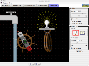
The [http://phet.colorado.edu/ University of Colorado] has graciously allowed us to use the following Phet simulation. This simulation<ref name=d></ref> illustrates how a simplified AC generator could work, with a water turbine rotating a magnet that induces an alternating current in the stationary armature. | The [http://phet.colorado.edu/ University of Colorado] has graciously allowed us to use the following Phet simulation. This simulation<ref name=d></ref> illustrates how a simplified AC generator could work, with a water turbine rotating a magnet that induces an alternating current in the stationary armature. | ||
<html> | <html> | ||
<div style="position: relative; width: 300px; height: 225px;"><a href=" | <div style="position: relative; width: 300px; height: 225px;"><a href="https://phet.colorado.edu/sims/cheerpj/faraday/latest/faraday.html?simulation=generator" style="text-decoration: none;"><img src="http://phet.colorado.edu/sims/faraday/generator-screenshot.png" alt="Generator" style="border: none;" width="300" height="225"/><div style="position: absolute; width: 200px; height: 80px; left: 50px; top: 72px; background-color: #FFF; opacity: 0.6; filter: alpha(opacity = 60);"></div><table style="position: absolute; width: 200px; height: 80px; left: 50px; top: 72px;"><tr><td style="text-align: center; color: #000; font-size: 24px; font-family: Arial,sans-serif;">Click to Run</td></tr></table></a></div> | ||
</html> | </html> | ||
== For Further Reading == | |||
For further information please see the related pages below: | |||
*[[Alternating current]] | |||
*[[Transformer]] | |||
*[[Electrical grid]] | |||
*[[Electric generator]] | |||
* Or explore a [[Special:Random| random page!]] | |||
==References== | ==References== | ||
<references/> | <references/> | ||
[[Category:Uploaded]] | [[Category:Uploaded]] | ||
[[Category:Phets]] | |||
Latest revision as of 16:53, 4 August 2021
Turbine-based AC electrical generation is when an electric current is induced by the interaction between charged particles and magnetic fields which converts the kinetic energy of the turbine into the kinetic energy of electrons. This is where a high energy society gets most of its electricity from. According to the law of conservation of energy, generators do not create energy. Rather, they convert a different form of energy into electrical energy. This form of electrical generation is used with all sources of energy that use the movement of a turbine. Examples of these include hydropower, fossil fuel-based power, nuclear energy, and solar thermal power plants, among others. Almost all major power plants generate alternating current, as do diesel generators.
Theory

Faraday's Law states that a changing magnetic flux on a looped conductor will produce a magnetic force that causes the electrons in the conductor to move, creating a current. This is known as electromagnetic induction, and it is the fundamental principle underlying many generators. The magnetic force applied to the electrons creates a voltage in the conductor that is known as an electromotive force. The strength and direction of the electromotive force is determined by the strength and direction of the magnetic field and the velocity of either the magnet or the conductor[2]. Electric motors work in the exact opposite way—electric current in a magnetic field creates motion.
See Figure 1 to see this theory in practice.
Generator

Electric current is generated when a rotating loop of wire, known as an armature, is placed in a uniform magnetic field, or when a stationary armature is placed in a rotating magnetic field. In the first case, as the armature rotates, one half of the loop will always be moving in the opposite direction of the other half of the loop. This causes an electromotive force in opposite directions for both halves of the armature, which add together to allow a current to flow through the loop (see Figure 1)[4]. The same result can be achieved with a rotating magnet around a stationary armature. This generation of current is entirely dependent on the armature or magnet rotating, and this rotation is powered by turbines, which rotate due to one of the sources of energy listed above. For more information, visit hyperphysics.
As seen in Figure 2, both of the arms of the armature are connected to slipping contacts called brushes[5]. One of the brushes is connected to a wire which connects to a power distribution system and eventually leads back to the wire connecting to the other brush, completing the circuit and allowing the generator to power devices. As the armature rotates, the segment of the velocity of the armature perpendicular to the magnetic field changes direction. In other words, each half of the armature periodically changes direction as the armature rotates. This leads the current to experience a periodic reversal of the direction. In addition, as the magnetic force is directly proportional to the segment of the velocity of the charge that is perpendicular to the magnetic field, the electromotive force in the circuit varies as the segment of the velocity of the armature perpendicular to the field varies. This sinusoidally varying voltage coupled with the periodically reversing current is characteristic of alternating current [4].
Phet Simulation
The University of Colorado has graciously allowed us to use the following Phet simulation. This simulation[1] illustrates how a simplified AC generator could work, with a water turbine rotating a magnet that induces an alternating current in the stationary armature.
| Click to Run |
For Further Reading
For further information please see the related pages below:
References
- ↑ 1.0 1.1 Generator [Online]. Available: http://phet.colorado.edu/en/simulation/generator
- ↑ Faraday's Law [Online]. Available: http://hyperphysics.phy-astr.gsu.edu/hbase/electric/farlaw.html#c1
- ↑ E. Hiob. (1998, June 11). electronics and trigonometry [Online]. Available: http://commons.bcit.ca/math/examples/elex/trig_vectors/
- ↑ 4.0 4.1 AC Generator [Online]. Available: http://hyperphysics.phy-astr.gsu.edu/hbase/magnetic/motorac.html#c2
- ↑ AC Motor [Online]. Available: http://hyperphysics.phy-astr.gsu.edu/hbase/magnetic/motorac.html