Hydraulic head: Difference between revisions
No edit summary |
J.williams (talk | contribs) m (1 revision imported) |
(No difference)
| |
Revision as of 18:23, 3 September 2015
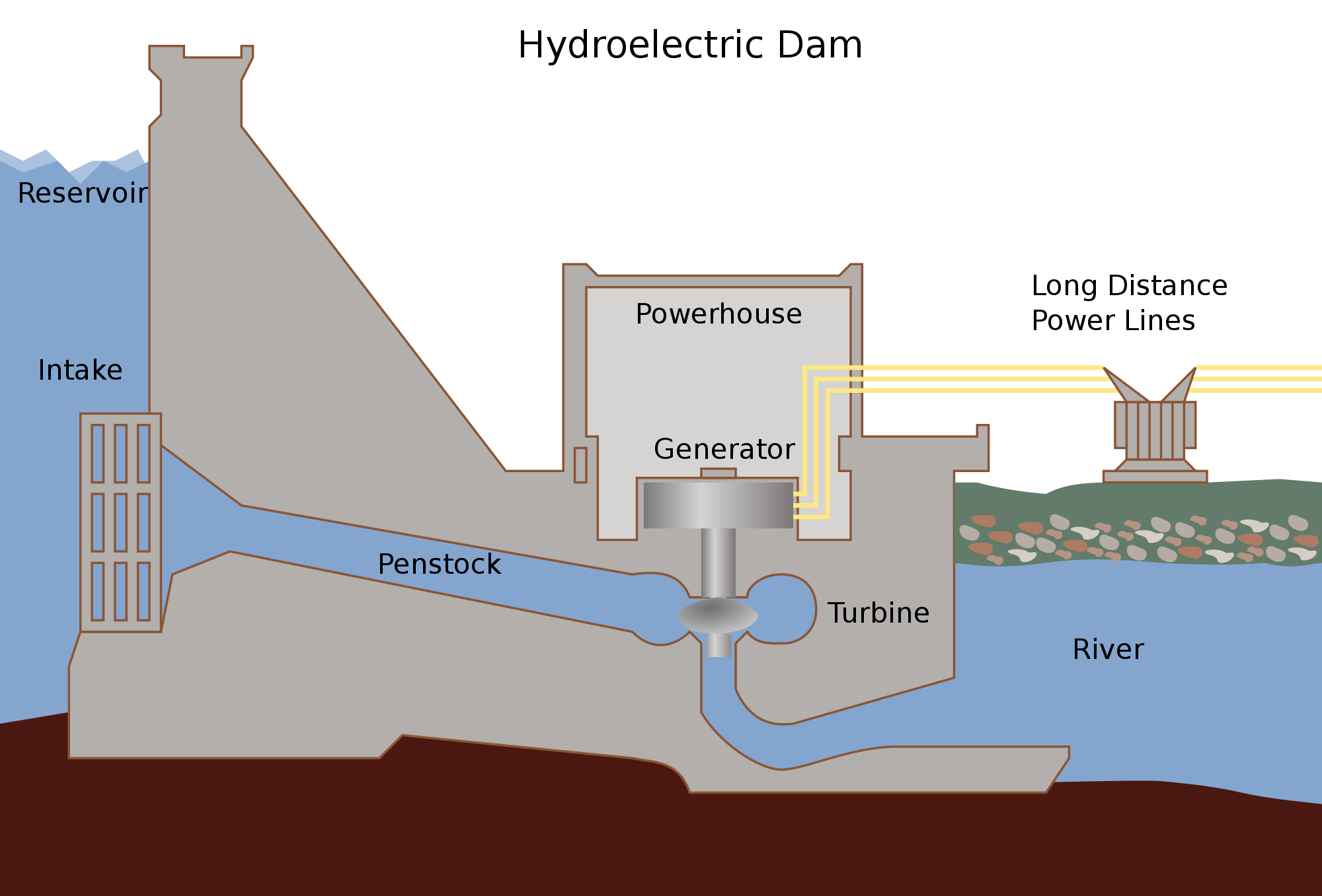
The hydraulic head is a value that represents the height that water 'falls' from a higher elevation reservoir where it is stored to the turbines where it is used to generate electricity.[1] This is simply a measurement of the difference in height as the water moves through the system, usually expressed in meters. This height difference includes the distance down through the penstocks and into the turbine itself. The larger the height of the hydraulic head, the more energy that the flowing water has.[2] The water in the reservoir, which is at a higher altitude has more gravitational potential energy because it is at a higher vertical position than the tail race. The energy used to generate electricity by moving the turbines arises from the transformation from gravitational potential energy of the reservoir water to kinetic energy of falling water as it moves down through the penstocks.

The value for hydraulic head is used in the hydroelectric power equation to determine the available power of a hydroelectric system. It is one of the main components in this equation, represented by:[1]
where:
is the amount of power being calculated, measured in joules per second (J/s) which is also known as a watt (W)
is the hydraulic head, expressed in meters (m)
is the density of the fluid, measured in kilograms per unit volume (kg/m3)
is the volumetric flow rate of the fluid, measured in volume per unit time (m3/s)
is acceleration due to gravity, measured in meters per second (m/s)
Note that the larger the h value in the expression above, the more gravitational potential energy the water in the reservoir has.
Classifications
There are three main classifications of hydraulic head: high, medium, and low. The characteristics of these types are described below.
High Head
Elevations 100 meters or higher are considered high head. In this type of plant, water travelling through the turbine comes from a significantly higher elevation, meaning that the system requires a smaller volume of water to operate since the water gains more momentum simply by falling.[1] These systems generally also require smaller turbines since there is less water flowing through the turbine.
In addition to a smaller turbine, a larger penstock is needed to guide the water down from the high elevation reservoir. Generally, large hydroelectric installations are either high or medium head.[2]
Medium Head
Medium head systems are an in-between between high and low head systems. Like high head dams, medium head dams contain a penstock that transports water from a reservoir down to the turbine. However, this penstock is slightly shorter as there is less of an elevation drop. This type of dam relies both on a significant volume of water flowing and a significant drop in height of the water.
Low Head
Low head is usually classified as systems with elevations of around 10 meters. These low head hydro turbines are generally used in run-of-the-river systems where there is a flowing river with little elevation change. In these dams, there is no penstock as there isn't enough of a water drop to justify its installation.[2]
These low head systems usually transport large volumes of water and thus require larger turbine generators to efficiently convert water energy into electricity. A dam isn't always needed in these low head systems, as there is very little water storage.[1]
Head Losses
Although there is a set height difference between the water reservoir and the tail race in a hydroelectric facilities, there are some losses that occur whenever water flows through the pipes. These losses reduce the overall head and result in a number known as the effective head.[1] Head losses occur in all hydroelectric facilities, and are classified as major and minor head losses. A head loss occurs in inefficiencies of the hydroelectric facility that reduce the total hydraulic head that can be used for hydroelectric generation. These hydraulic head losses are measured, calculated, and expressed in the same way hydraulic head is, in meters. Once hydraulic head losses are known they can simply subtracted from the hydraulic head to get the total hydraulic head.
Types of head losses include:[4]
- Major head losses: Major head losses arise from factors such as surface friction from the pipes, length of the pipes, and size of pipes
- Minor head losses: Minor head losses arise from friction at bends and valves, flow rate in the pipe, and blockages such as trash racks
Major head losses are typically expected to be larger then minor head losses. The minor head losses can actually contribute more to the total head loss than the major head losses do. These arise fromthe design of the hydroelectric facility, limitations in the local geography, river flow, size of river, and type of river.[4]
References
- ↑ 1.0 1.1 1.2 1.3 1.4 G. Boyle. Renewable Energy: Power for a Sustainable Future, 2nd ed. Oxford, UK: Oxford University Press, 2004.
- ↑ 2.0 2.1 2.2 Turbine Generator. (August 31, 2015). Hydraulic Head [Online]. Available: http://turbinegenerator.org/hydro/hydroelectric-power/hydraulic-head
- ↑ Wikimedia Commons. (August 31, 2015). Hydroelectric Dam [Online]. Available: https://upload.wikimedia.org/wikipedia/commons/thumb/5/57/Hydroelectric_dam.svg/2000px-Hydroelectric_dam.svg.png
- ↑ 4.0 4.1 The Engineering Toolbox. (August 31, 2015). Total Pressure or Head Loss in Pipe or Duct Systems [Online]. Available: http://www.engineeringtoolbox.com/total-pressure-loss-ducts-pipes-d_625.html